Solar Panel & Battery Systems Built to Last.
Reduce your upfront battery cost with a rebate eligible installation.
Speak to an expert4.8
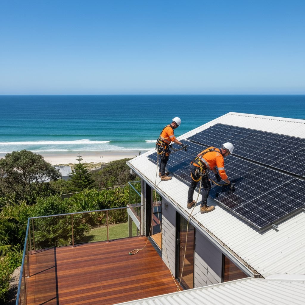
Australia’s longest-serving solar company
Powering homes communities since 1987.
$50M+
IN RENEWABLE PROJECTS
2,000 MWh
OF CLEAN ENERGY EACH YEAR
38+ Years
OF SOLAR INNOVATION
35+
TEAM MEMEBERS NATIONALLY
SMART ENERGY SERVICES
Energy solutions built for every need
ENQUIRE HEREOn Grid
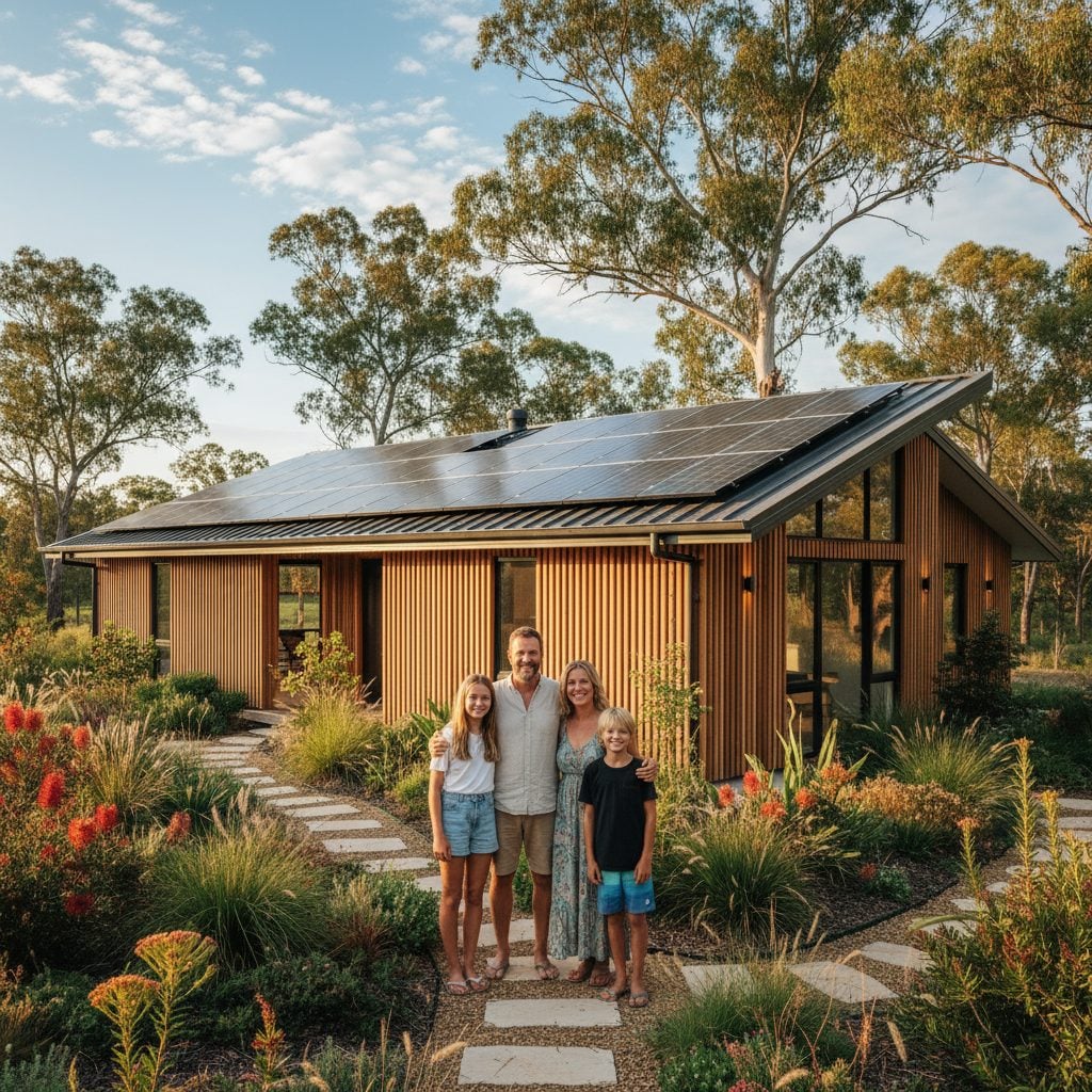
Smarter Power for Homes and Businesses
Save on electricity with reliable, Australian-built on-grid solar systems. Add battery storage for blackout protection and long-term energy independence.
Explore
Off Grid
Reliable Power, Wherever You Are
From small cabins to large estates, our off-grid solar systems deliver 24/7 electricity built for Australian conditions, no grid required.
Explore
Community
Empowering Communities with Shared Energy
We partner with schools, councils, and local organisations to design solar systems that strengthen community infrastructure and create lasting sustainability.
Explore
Commercial
Powering Business Efficiency
Our commercial solar systems cut costs, boost energy independence, and deliver reliable performance for industrial, retail, and agricultural operations.
Explore
International
Sustainable Power Across the Pacific
Since 1987, RPC has designed and delivered off-grid and hybrid solar projects across eight countries, powering resorts, schools, and remote communities.
Explore


EXPERTS IN SOLAR
EV charger solutions for homes and businesses
Since 1987, Rainbow Power Company has designed and delivered solar and battery systems built for long term performance, not short term installs.
EV charging is not treated as a separate add on. It is integrated into your solar, battery and overall energy system to ensure everything works together properly.
We focus on systems that perform reliably, reduce grid reliance, and continue delivering value well into the future.

Expert advice, no guesswork.
We design around your usage, site and future needs, not a generic package. Every system is planned to ensure your EV charging works seamlessly with your solar and battery setup.
Proven technology, properly integrated.
We use trusted suppliers and components that are selected to work together, ensuring reliable performance in Australian conditions.
Local team, long term support
Real support after installation, including monitoring, upgrades and system optimisation as your energy needs change.
MORE ENERGY, MORE SAVING
Energy Freedom, Made Easy With RPC
Take control of your energy future with solar solutions built for Australian conditions. Enjoy lower bills, reduced emissions, and dependable power both on and off the grid.
At RPC, we design solar systems for maximum efficiency. By optimising panel orientation and placement, we help you capture more sunlight, lower your costs, and achieve lasting energy independence.
At RPC, we design solar systems for maximum efficiency. By optimising panel orientation and placement, we help you capture more sunlight, lower your costs, and achieve lasting energy independence.
SOLAR CALCULATOR
YOUR LOCAL SOLAR EXPERTS
Find your local RPC
Servicing from the Tweed to Grafton and everywhere between.
Based in Nimbin, we power the Northern Rivers, and supply off-grid systems Australia-wide.
40k+
Installations
0+
Yrs Experience
0k+
Projects
Your Solar Journey
It’s simple to switch to smart, cost-effective solar with RPC
REQUEST A PERSONALISED QUOTE


Step 1
Request Your Quote
Send us your details online or by phone. Our team will assess your property, usage, and goals to find the right system for your needs.
Step 2
Personalised Energy Plan
We’ll design a tailored solar plan showing system size, rebates, and estimated savings, including how quickly it can pay for itself.
Step 3
Expert Installation
Once approved, our qualified installers set up your system safely, efficiently, and at a time that suits you.
Step 4
Ongoing Support
Enjoy peace of mind with dedicated after-sales care, system checks, and expert advice from Australia’s longest-serving solar team.
What our customers are saying
EXPERT GUIDANCE
Tap into our solar knowledge base
Explore practical insights, tips, and how-tos from Australia’s trusted solar experts. Learn how solar works, what makes it efficient, and why it’s a smart long-term investment.
Learn More


WE'RE HERE TO HELP
Frequently asked questions
What areas do you service?
We install systems across the Northern Rivers and South East Queensland, and supply packaged off-grid systems Australia-wide.
Do you offer finance options?
Yes, we partner with trusted lenders to provide flexible finance, making solar more accessible for homeowners and businesses.
Can I add a battery to my existing system?
Absolutely. We can retrofit battery storage to most systems, helping you store more of your own energy and cut grid costs.
How long does installation take?
Typical on-grid systems are installed in 1–2 days. Larger off-grid and commercial projects vary depending on site and design.
What kind of after-sales support do you offer?
RPC provides ongoing support, maintenance advice, and technical assistance for the lifetime of your system.